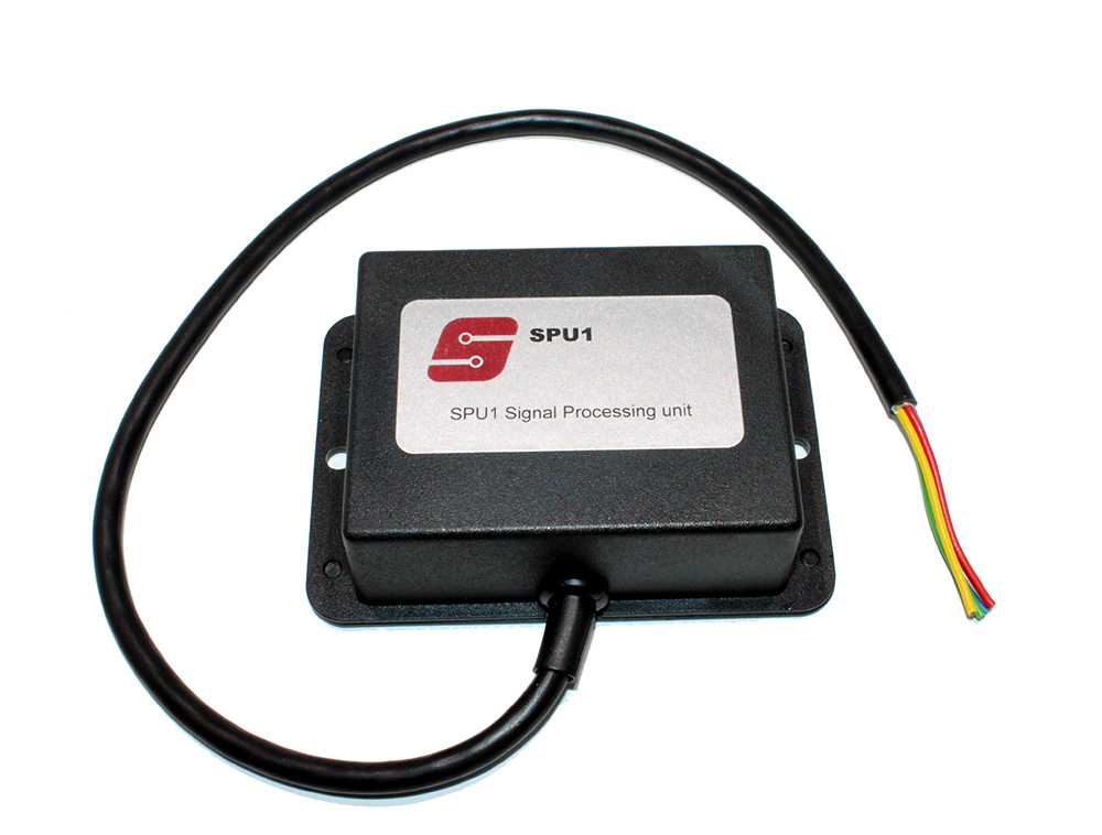
SPU1 – Signal Processing Unit
Special Price Please call us on +44 (0)1386 554 210 for more details
Part No: SPU1 Speed Pulse Interface
The Signal Processing Unit is designed to accept and process speed pulse signals.
Automobile manufacturers use different techniques to generate speed related signals. Unfortunately there is no standard for these signals. Rotary movement of the transmission or a wheel component is converted into a pulsating electrical signal.
The technique used to generate this signal will determine its amplitude, pulse shape and frequency.
Pulsating electrical signals occur when a pulsating voltage is generated in a circuit. The pulsating voltage will drive a pulsating current through the circuit.
In a typical installation, the pulsating voltage is generated close to the rotating component by a unit called a transducer. This drives a pulsating current through a wiring harness to a detecting device. (Speedometer, Tachograph, Navigation System etc). The pulsations in the signal are extracted and scaled to give vehicle speed, and are counted and scaled to give distance travelled.
A pulsating current CAN ONLY FLOW if there is an outward AND a return electrical path to the transducer, or signal source.
In order for the SPU1 (or any of our interface units) to operate correctly, it is essential to find and identify BOTH paths. The return path could be the vehicle chassis, but very often it is a separately run wire, which is bonded to the chassis or the common.
The signal from the transducer will only pulsate when the vehicle is moving or the wheels are rotating on a rolling road. It can be very difficult to identify the appropriate wires without rolling road facilities.
Fig 2 shows a pulsating waveform from a transducer and identifies the terms Amplitude, Pulse Shape and Frequency.
The pulse width defines a pulse shape, which repeats at regular intervals. The number of repetitive pulse shapes per second defines the Frequency.
When the SPU1 interface is connected to this signal input, it converts the repetitive pulse shapes into square shaped pulses. The frequency of the processed pulses can be changed to be a fixed ratio of the frequency of this input. The processing is controlled using the on board switches and by selecting appropriate input and output terminals.
The SPU1 interface is designed to operate on a 12 volt DC electrical system. For ease of installation the preferred option is a “negative earth” battery configuration. It will operate down to 9 volts and up to 16 volts. It should not be used on 24 volt battery vehicles. Reverse voltage protection is included to guard against reversed wiring of the unit.
Although vehicles operate with a 12 volt battery supply, many automotive instruments using electronic circuits and some navigation kits prefer 5 volt signals. The SPU1 can be switched to deliver a signal amplitude of 5 volts or 12 volts. If the requirements of the instrument are not known, then start with the 5 volt options selected on the SPU1.
Fig 3 shows how SPU1 deals with the pulsating signal of Fig 2.
The terminal block of SPU1 is marked with + – 1 2 3 4 5 6 Connections should be made as follows:
+ Connect to a good 12 volt supply.
– Connect indirectly to battery negative. This is probably the most critical connection to the SPU1. If the flow and return paths of the transducer have been correctly identified, then this terminal should be connected to A or B on Fig 1. (Whichever is appropriate)
With these connections made the test LED on the board will flash rapidly when the frequency selection switch is on position 0. This is the test mode. On other positions the LED will be either on or off and will not flash until an input signal is connected and the wheels rotate.
Terminal connections 1 2 3 and 4 are outputs from SPU1.
1 and 2 are voltage output switches. The switches operate in anti-phase (i.e. they are inverted drives. When one is at high voltage then the other is at low voltage). This allows the interface to drive models of tachograph which need both normal and inverted signals to operate correctly.
The voltage output levels from 1 and 2 can be independently adjusted to give 5 or 12 volt outputs using the 2-way DIL switch. (See Fig 4)
3 and 4 are open collector (volt free). These will only drive an instrument or nav kit, which is designed to operate with open collector or volt free switched output. The only difference between 3 and 4 is the polarity of the switch contacts. 3 is ON when 4 is OFF and vice-versa. (a requirement of some tachographs where both need to be connected)
If the inverted output facility is not required for the connection of tachographs then all four outputs can be used to drive individual instruments. (If an instrument requires a voltage drive, it can be used by adding an external 4K7 pull-up resistor to 1 and 2. (Call for instructions).
Input Circuits for the speed pulses Terminals 5 and 6 offer different sensitivities for the speed pulses.
Use terminal 5 for most installations. This accepts signals in the range 0.5 volt to 12 volt.
Some speed signal transducers require an external pull-up resistor. This can be provided by using switch 4 on the 4-way DIL switch. (The factory setting is OFF. Switch to ON if a pull-up is required.)
The overload characteristic of this input allows it to withstand ± 30 volt continuously without damage.
If the signal is below 0.5 volt then terminal 6 can be used. The sensitivity of this input extends down to 50 millivolt. However special wiring techniques may be required to reduce external interference and interference generated by the vehicle electrics. (Obtain specialist advice if not familiar with handling low level signals)
Vehicle electrics often generate electrical “noise”. This can add to the transducer signal and produce spurious results. The SPU1 has three levels of input filtering. Switches 1, 2, and 3 on the 4-way DIL switch control this filtering. The unit is shipped with 1 switched ON.
To increase the filtering switch 2 to ON. For more filtering switch 3 to ON.
Remember that filtering removes higher frequency components from the signal. Speed signals increase in frequency as the speed increases. A filter level, which allows the unit to operate correctly at low speeds, may adversely affect the performance at high speeds. The unit is shipped with filter 1 switched ON. This should be adequate for the majority of installations. If 2 and/or 3 are used then check the performance of the system at the maximum expected vehicle speed.
Function Switch Positions. Position 0 = Self Test
Pos 1 2 3 4 5 6 7 8 9 A B C D
Ratio 1:1 2:1 4:1 6:1 8:1 12:1 16:1 24:1 32:1 48:1 64:1 96:1 128:1
Pos E and F multiply by 2 E generates a 31 millisec pulse; F a 12 millisec pulse